DC netwerken
Rseries
Series connection of resistors
Rseriesparallel
Series and parallel connection of resistors
RC
RC transient response and AC transfer function
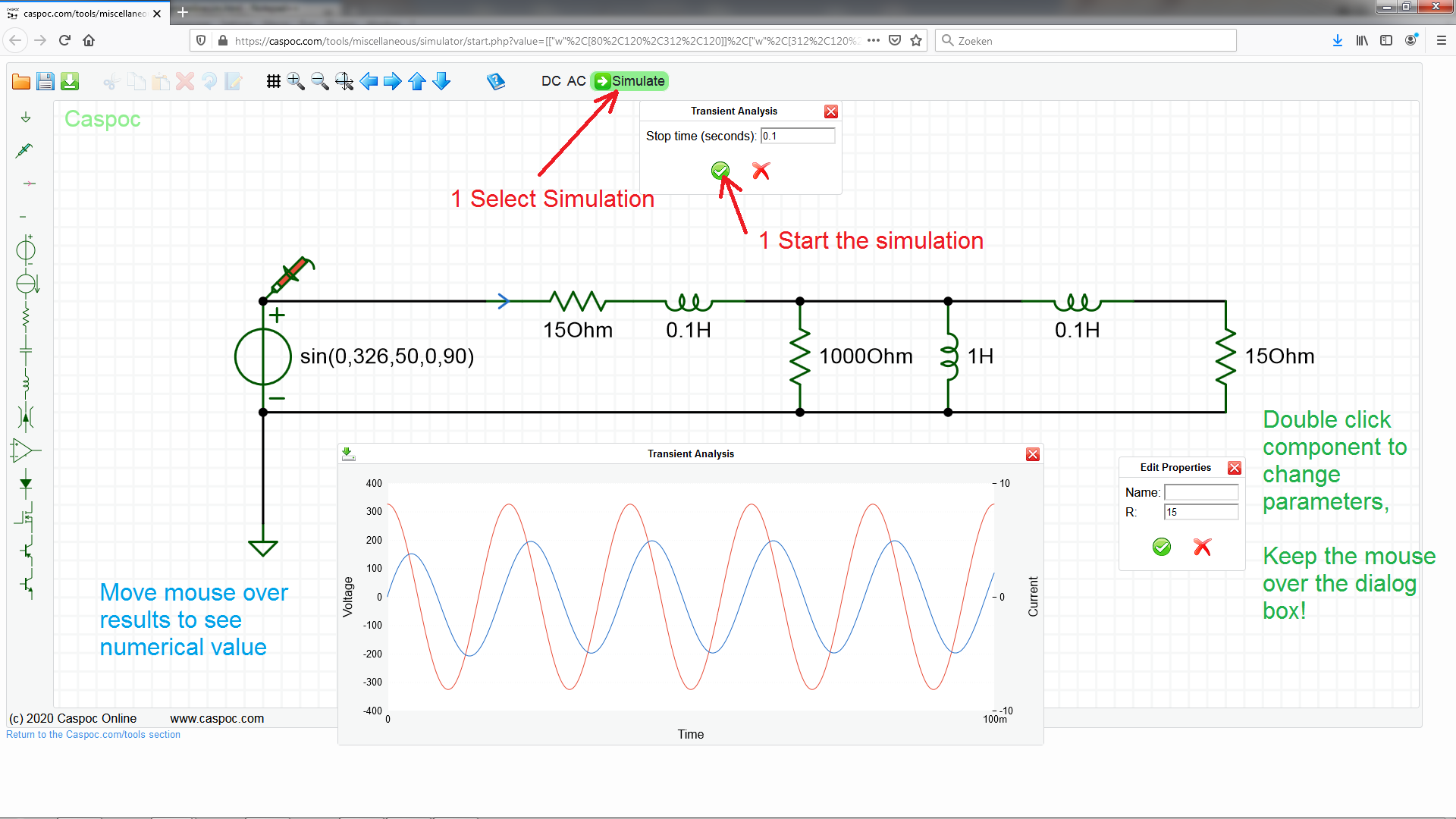
RL
RL transient response and AC transfer function
RLC
RLC transient response and AC transfer function
AC Netwerken
RL 3phase L=10mH R=10Ohm
RL 3phase L=10mH R=10Ohm
RL 3phase L=10mH R=1Ohm
RL 3phase L=10mH R=1Ohm
RL 3phase L=10mH R=10Ohm R1=5ohm Unbalance
RL 3phase L=10mH R=10Ohm R1=5ohm Unbalance
Third Harmonics 15V
Third Harmonics 15V
Third Harmonics 45V Maximum voltage is now lower
Third Harmonics 45V Maximum voltage is now lower
Space Vector Modulation
Space vector modulation, injection of triangle third harmonic
Inverters
Half Bridge
Half Bridge
FullBridge
Full bridge
Asynchrone machine
Nominal
S=4 percent slip
No Load
S=0 percent slip
Locked Rotor
S=100 percent slip
Delay start up
Delay circuit for keeping Shut Down Gate Driver Low
Switched Mode Power Supplies
Laboratory exercises VRMEL/ELOMVO 2022/2023
Buck converter
First simulate the buck converter and observe the waveforms. In the default simulation the conversion is from 48volt down to 12 volt.
Parameters of the simulation:
| Component | Value |
|---|
| Vin | 48volt |
| L | 220uH |
| C | 10uF |
| Rout | 10 |
| Fs | 50kHz |
| d | 25% |
Buck Converter 48volt->12volt
Change the duty cycle while the input voltage remains 48 volt. Measure input current, output voltage and current, calculate input and output power as well as the efficiency of the converter and fill the table below:
| d | Vin | Iin | Vout | Iout | Pin | Pout | η |
|---|
| 10 | 48 | | | | | | |
| 20 | 48 | | | | | | |
| 30 | 48 | | | | | | |
| 40 | 48 | | | | | | |
| 50 | 48 | | | | | | |
| 60 | 48 | | | | | | |
| 70 | 48 | | | | | | |
| 80 | 48 | | | | | | |
| 90 | 48 | | | | | | |
Use the default duty cycle of 25% and the input voltage remains 48 volt. Change the load resistance Rout from 2Ω in steps of 2Ω until 20Ω. Measure input current, output voltage and current, calculate input and output power as well as the efficiency of the converter and fill the table below:
| Rout | Vin | Iin | Vout | Iout | Pin | Pout | η |
|---|
| 2 | 48 | | | | | | |
| 4 | 48 | | | | | | |
| 6 | 48 | | | | | | |
| 8 | 48 | | | | | | |
| 10 | 48 | | | | | | |
| 12 | 48 | | | | | | |
| 14 | 48 | | | | | | |
| 16 | 48 | | | | | | |
| 18 | 48 | | | | | | |
| 20 | 48 | | | | | | |
Inductor current ripple
Dependency of inductor current ripple on the inductor value. Measure the inductor current ripple. Parameters of the simulation:
| Component | Value |
|---|
| Vin | 48volt |
| L | 100uH |
| C | 10uF |
| Rout | 10 |
| Fs | 50kHz |
| d | 40% |
Buck Converter 48volt->20volt, 50kHz
| Inductor | Inductor current ripple (top-top) [A] |
|---|
| 47μ | |
| 100μ | |
| 150μ | |
| 220μ | |
| 470μ | |
Change the switching frequency from 50kHz to 100kHz. Measure the inductor current ripple. Parameters of the simulation:
| Component | Value |
|---|
| Vin | 48volt |
| L | 100uH |
| C | 10uF |
| Rout | 10 |
| Fs | 100kHz |
| d | 40% |
Buck Converter 48volt->20volt, 100kHz
| Inductor | Inductor current ripple (top-top) [A] |
|---|
| 47μ | |
| 100μ | |
| 150μ | |
| 220μ | |
| 470μ | |
Output voltage ripple
Dependency of output voltage ripple on the capacitor value. Measure the peak-peak output voltage ripple. Parameters of the simulation:
| Component | Value |
|---|
| Vin | 48volt |
| L | 100uH |
| C | 10uF |
| Rout | 10 |
| Fs | 50kHz |
| d | 40% |
Buck Converter 48volt->20volt, 50kHz
| Capacitor | Output voltage ripple (top-top) [V] |
|---|
| 10μ | |
| 22μ | |
| 47μ | |
| 100μ | |
| 220μ | |
| 470μ | |
Change the switching frequency from 50kHz to 100kHz. Measure the peak-peak output voltage ripple. Parameters of the simulation:
| Component | Value |
|---|
| Vin | 48volt |
| L | 100uH |
| C | 10uF |
| Rout | 10 |
| Fs | 100kHz |
| d | 40% |
Buck Converter 48volt->20volt, 100kHz
| Capacitor | Output voltage ripple (peak-peak) [V] |
|---|
| 10μ | |
| 22μ | |
| 47μ | |
| 100μ | |
| 220μ | |
| 470μ | |
Output capacitor ESR
Dependency of output voltage ripple on the capacitor equivalent series resistance Resr value. Measure the peak-peak output voltage ripple. Parameters of the simulation:
| Component | Value |
|---|
| Vin | 48volt |
| L | 100uH |
| C | 10uF |
| Resr | 100m |
| Rout | 10 |
| Fs | 50kHz |
| d | 40% |
Buck Converter 48volt->20volt, Resr=100m
The esr of the output capacitor varies per type of capacitor. It is modelled by a an external resistor Resr, in series with the output capacitor. Measure the influence of the value of Resr on the output voltage ripple.
| Resr[Ohm] | Output voltage ripple (top-top) [V] |
|---|
| 1m | |
| 10m | |
| 100m | |
| 200m | |
| 500m | |
| 1 | |
Output capacitor ESR reduction
The output voltage ripple is reduced by placing two output capacitors in parallel.
Measure the peak-peak output voltage ripple. Parameters of the simulation:
| Component | Value |
|---|
| Vin | 48volt |
| L | 100uH |
| C(2*) | 10uF |
| Resr | 1 |
| Rout | 10 |
| Fs | 50kHz |
d | 40% |
Buck Converter 48volt->20volt, parallel output capacitor
Measure the influence of the paralleling of the output capacitors on the output voltage ripple.
| Capacitor | Output voltage ripple (top-top) [V] |
|---|
| 2 * 10μ | |
| 1 * 22μ | |
For the single capacitor simulation, change the value of Resr2 into 1000&Ohm;
| Explain the reduction of the output voltage ripple in case of the parallel output capacitor, compared to the single output capacitor. |
|---|
|
Waveforms Buck Converter, continuous inductor current
In the first simulation we will operate the buck converter with continuous inductor current. Parameters of the simulation:
| Component | Value |
|---|
| Vin | 48volt |
| L | 100uH |
| C | 10uF |
| Rout | 10 |
| Fs | 50kHz |
| d | 40% |
Buck Converter 48volt->20volt, continuous inductor current
For each simulation, measure either the output voltage or the voltage at the node between the Mosfet and the Diode.
| Waveform1 | Waveform2 |
|---|
| IL | Vout |
| IL | Vleg | (between the Mosfet and Diode)
Create the graphs for the above mentioned waveforms.
For each simulation, add a single current measurement sensor to measure the current through the Mosfet, Diode, Cout, Rout, Vin.
| Waveform1 | Waveform2 |
|---|
| IL | IDS |
| IL | ID |
| IL | IC |
| IL | IR |
| IL | Iin |
Create the graphs for the above mentioned waveforms.
Waveforms Buck Converter, discontinuous inductor current
In the second simulation we will operate the buck converter with discontinuous inductor current. Parameters of the simulation:
| Component | Value |
|---|
| Vin | 48volt |
| L | 22uH |
| C | 10uF |
| Rout | 10 |
| Fs | 50kHz |
| d | 40% |
Buck Converter 48volt->20volt, discontinuous inductor current
For each simulation, measure either the output voltage or the voltage at the node between the Mosfet and the Diode.
| Waveform1 | Waveform2 |
|---|
| IL | Vout |
| IL | Vleg | (between the Mosfet and Diode)
Create the graphs for the above mentioned waveforms.
For each simulation, add a single current measurement sensor to measure the current through the Mosfet, Diode, Cout, Rout, Vin.
| Waveform1 | Waveform2 |
|---|
| IL | IDS |
| IL | ID |
| IL | IC |
| IL | IR |
| IL | Iin |
Create the graphs for the above mentioned waveforms.
Synchronous Buck Converter
Synchronous Buck Converter 48volt->12volt
Simulation Buck Converter
Buck converter 50%
Simulation Boost Converter
Boost converter 66%
Simulation Buck-Boost Converter
BuckBoost converter 50%
Simulation Boost Converter ideal components discontinuous mode
Boost converter Ideal
Simulation Boost Converter discontinuous mode with Mosfet output capacitance modeled
Boost converter output capacitance Mosfet
Simulation U4L Single leg
Single Leg U4L
Simulation U4L Blanking time
Single Leg blanking time
Simulation U4L with Blanking time and start up
Single Leg blanking time
Simulation Mosfet Switching transients
Mosfet Switching
Simulation Mosfet Gate charge
Gate Charge
LC filter response
RLC Filter
LC filter input Impedance
Select [AC]
Input Impedance LC Filter
Help